The Starting Sequence at a Glance
Turning a key or pressing a start button triggers one of the most precisely coordinated electrical-mechanical sequences in your vehicle. Within a fraction of a second, battery current travels through a relay, energizes a solenoid, engages a gear, and spins an engine fast enough to initiate combustion. Understanding each step helps you recognize symptoms when something in the chain fails.
| Typical starter current draw | 100-200+ amperes (General industry specification range) |
| Gasoline engine cranking speed | 150-250 RPM minimum (General automotive engineering reference) |
| Ignition switch signal voltage | ~12 V (low amperage control signal) (Standard 12 V automotive electrical systems) |
| Solenoid plunger functions | 2 - mechanical gear engagement + circuit closure |
| Stages in the starting sequence | 3 - ignition/relay, solenoid, starter motor |
The sequence breaks into three overlapping stages: the ignition switch sending a signal, the solenoid acting as a high-current switch and mechanical actuator, and the starter motor physically cranking the engine. Each stage depends entirely on the one before it.
Stage 1 - The Ignition Switch and Starter Relay
The ignition switch is a low-current control device. When you turn it to the Start position, it sends a small signal voltage - typically 12 V at very low amperage - to a starter relay (sometimes called the starter solenoid relay). This relay acts as a gate: it uses that small signal to close a heavier-duty circuit capable of carrying the large current the starter motor demands.
Many modern vehicles add an additional layer here: the Body Control Module (BCM) or a dedicated start/stop module verifies conditions - clutch pedal depressed (manual), brake pedal depressed (automatic), anti-theft status - before allowing the relay to close. If any condition is unmet, the relay never activates and the engine will not crank.
Starter Solenoid
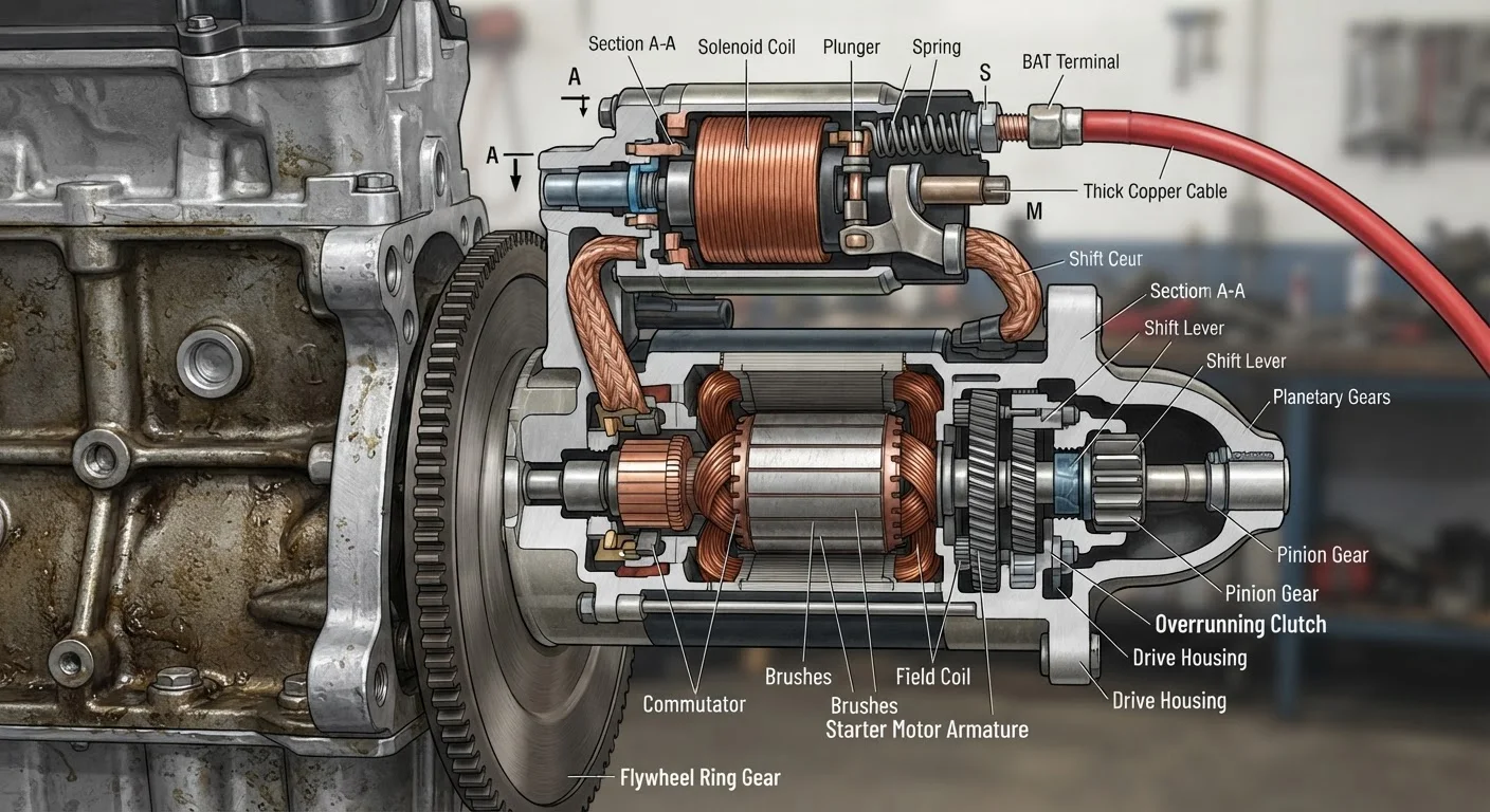
An electromagnetic switch mounted on the starter motor that simultaneously meshes the drive pinion with the ring gear and closes the high-current circuit to the motor. It performs both a mechanical and electrical function in a single stroke.
Ring Gear
A large toothed gear attached to the outer edge of the engine's flywheel (manual transmission) or flexplate (automatic). The starter motor's pinion meshes with it to rotate the crankshaft during cranking.
Overrunning Clutch (Bendix Drive)
A one-way mechanical device inside the starter's drive assembly that allows the engine ring gear to spin faster than the pinion once the engine starts, preventing the engine from back-driving and over-speeding the starter motor.
Cranking Speed
The minimum rotational speed - typically 150-250 RPM for gasoline engines - that an engine must reach during starting before the fuel and ignition systems can sustain combustion independently.
Starter Relay
A low-current-controlled switch that gates the high-current circuit between the battery and the starter solenoid. It protects the ignition switch from carrying the large amperage the starting system requires.
Drive Pinion
The small gear on the end of the starter motor's output shaft that extends outward to mesh with the ring gear when the solenoid plunger is activated.
Stage 2 - The Solenoid Engages
Once the relay closes, full battery current flows to the starter solenoid, which is typically mounted directly on the starter motor housing. The solenoid has two jobs simultaneously:
- Mechanical: An electromagnetic coil pulls a plunger inward. That plunger pushes the starter's drive pinion gear outward along a spiral shaft, meshing it with the engine's ring gear - the large toothed gear on the outer edge of the flywheel or flexplate.
- Electrical: At the end of its travel, the plunger bridges two heavy copper contacts inside the solenoid, completing the main high-current circuit to the starter motor itself.
This two-step action ensures the pinion gear is fully engaged before the motor begins spinning - preventing the teeth from clashing at speed, which would damage both gears.
Stage 3 - The Starter Motor Cranks the Engine
With the circuit complete, current - commonly 100-200 amperes or more - flows through the starter motor's field windings and armature. The motor converts this electrical energy into rotational force (torque), spinning the pinion gear and, through the ring gear, rotating the engine's crankshaft.
The engine must reach a minimum rotational speed - called cranking speed, typically 150-250 RPM for gasoline engines - before the fuel-and-ignition system can sustain combustion on its own. Once the engine fires and exceeds starter speed, an internal overrunning clutch (also called a Bendix drive) allows the ring gear to spin faster than the pinion without back-driving the starter motor, protecting it from damage.
100-200 A
Current drawn by a starter motor during cranking
Starter motors are among the highest instantaneous current consumers in a standard 12 V automotive electrical system.
< 1 second
Time for the solenoid to fully engage the pinion
The entire mechanical engagement of the solenoid plunger and pinion gear occurs in well under one second during a normal start.
Releasing the key or button de-energizes the solenoid, retracting the plunger and pinion. The starter is fully disengaged before engine RPM climbs into its normal idle range.
If your vehicle cranks slowly, clicks once, or does not crank at all, the fault usually lies at a specific point in this sequence. See our systematic no-start diagnosis guide to trace the failure logically. For deeper context on what happens once the engine is running, the anatomy of a high-performance engine explains how combustion and valve timing sustain that power.
This article is intended for general educational purposes. Electrical system work involves high current and the risk of injury or vehicle damage. Consult a qualified mechanic for diagnosis or repair of starting system components.